LED INTERFACING WITH ARDUINO
LEDs are small, powerful lights that are used in many different applications. In this tutorial you will know how to interface LEDs with Arduino (using ATmega328p).
Synopsis

LEDs are small, powerful lights that are used in many different applications. A light emitting diode (LED) is a semiconductor device that emits visible light when an electric current passes through it. The light is not particularly bright, but in mostLEDsĀ it is monochromatic, occurring at a single wavelength. Arduino is a set of development boards that come with pre-tested hardware and software libraries. It means, you can by an Arduino board and start developing your project instantly. The boards are built around the AVR micro controller as the base. Here we are using the ATmega328p AVR 8-bit microcontroller to develop an Arduino board. The Atmel ATmega328p is a low power CMOS 8-bit controller based on the AVR enhanced RISC architecture.

Description

The Arduino Uno is a microcontroller board based on the ATmega328(datasheet). It has 14 digital input/output pins (of which 6 can be used as PWM outputs), 6 analog inputs, a 16 MHz ceramic resonator, a USB connection, power jack, an ICSP header, and a reset button. It contains everything needed to support the microcontroller; simply connect it to a computer with a USB cable or power it with an AC-to-DC adapter or battery to get started.

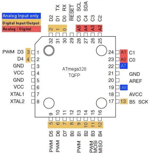
Specifications of Arduino:

>> Microcontroller ATmega328p

>> Operating Voltage 5V

>> Input Voltage (recommended) 7-12V

>> Input Voltage (limits) 6-20V

>> Digital I/O Pins 14 (of which 6 provide PWM output)

>> Analog Input Pins 6

>> DC Current per I/O Pin 40 mA

>> DC Current for 3.3V Pin 50 mA

>> Flash Memory 32 KB (ATmega328) of which 0.5 KB used by bootloader

>> SRAM 2 KB (ATmega328p)

>> EEPROM 1 KB (ATmega328p)

>> Clock Speed 16 MHz

The Arduino Uno has a number of facilities for communicating with a computer, another Arduino, or other microcontrollers. The ATmega328p provides UAR TTL [Universal Asynchronous Receiver and Transmitter] (5V) serial communication, which is available on digital pins 0 (RX) and 1 (TX). A Software Serial library allows for serial communication on any of the Uno's digital pins. The ATmega328p also supports I2C (TWI) and SPI [Serial Peripheral Interface] communication. The Arduino software includes a Wire library to simplify use of the I2C bus.

TTL level UART

Most microcontrollers with UART uses TTL (Transistor-transistor Logic) level UART. It is the simplest form of UART. Both logic 1 and 0 are represented by 5V and 0V respectively.

Voltage level for TTL level UART


The TTL level UART is commonly used in the communications between microcontrollers and ICs. Only 2 wires are required for the full duplex communications.

Programming

The Arduino Uno can be programmed with the Arduino software.The ATmega328 on the Arduino Uno comes preburned with a bootloaderthat allows to upload new code to it without the use of an external hardware programmer. It communicates using the original STK500 protocol (A protocol is a set of rules and guidelines for communicating data. Rules are defined for each step and process during communication between two or more computers. The STK500 is a complete starter kit and development system for the AVR Flash Microcontroller from Atmel Corporation.). We can also bypass the bootloader and program the microcontroller through the ICSP (In-Circuit Serial Programming) header.The Arduino software uses this capability to allow you to upload code by simply pressing the upload button in the Arduino environment. This means that the bootloader can have a shorter timeout, as the lowering of DTR can be well-coordinated with the start of the upload.

The Arduino Uno has a resettable polyfuse that protects your computer's USB ports from shorts and overcurrent. Although most computers provide their own internal protection, the fuse provides an extra layer of protection. If more than 500 mA is applied to the USB port, the fuse will automatically break the connection until the short or overload is removed.Rather than requiring a physical press of the reset button before an upload, the Arduino Uno is designed in a way that allows it to be reset by software running on a connected computer.

Below is the ATmega328p and Arduino pin mapping. Here 13, 14 and 15 pins in ATmega328p microcontroller represents as digital I/O pins [D9, D10, D11] of Arduino. In Arduino IDE software we give pin numbers 9, 10, 11 instead of 13, 14, 15.


Proteus design for LED interfacing with Arduino


Orcad design for LED interfacing with Arduino


LED interfacing with Arduino

/*  Name     : main.c
 *  Purpose  : Source code for LED Interfacing with ATmega328p.
 *  Author   : Gemicates
 *  Date     : 27-12-2017
 *  Website  : www.gemicates.org
 *  Revision : None
 */
 
#include "Arduino.h"

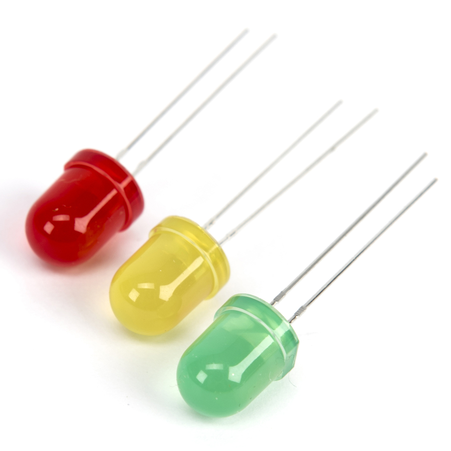
// Pin 9, 10, 11 have LED's connected on Arduino board

const int LED1 = 9, LED2 = 10, LED3 = 11;

// the setup routine runs once when you press reset

void setup()
{
  pinMode(LED1, OUTPUT);                        // initialize the digital pins as an output
  pinMode(LED2, OUTPUT);
  pinMode(LED3, OUTPUT);
}

// the loop routine runs over and over again forever

void loop()

{
  digitalWrite(LED1, HIGH);                     // turn the LED1 ON by making the voltage level HIGH
  delay(100);                                   // function call for delay
  digitalWrite(LED1, LOW);                      // turn the LED1 OFF by making the voltage LOW
  delay(100);                                   // function call for delay 
  digitalWrite(LED2, HIGH);                     // turn the LED2 ON by making the voltage level HIGH
  delay(100);                                   // function call for delay
  digitalWrite(LED2, LOW);                      // turn the LED2 OFF by making the voltage LOW
  delay(100);                                   // function call for delay
  digitalWrite(LED3, HIGH);                     // turn the LED3 ON by making the voltage level HIGH
  delay(100);                                   // function call for delay
  digitalWrite(LED3, LOW);                      // turn the LED3 OFF by making the voltage LOW
  delay(100);                                   // function call for delay
}


Error message here!

Show Error message here!


Forgot your password?

Error message here!

Send OTP

Error message here!

Show Error message here!


Lost your password? Please enter your email address. You will receive a password you Need.

Send Error message here!


Back to log-in

Close